Table of contents
Modeling the action of forces using plane simplification.
A force exerted by a flexible cable, belt, chain or rope is always a tensile force (away from the body) and cannot be negative (compressive) force.
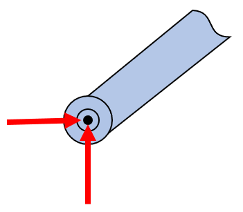
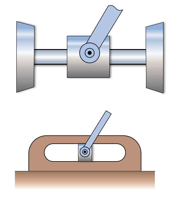
The right side of the beam is modelled as a pin connection that can freely rotate around a rigid pin support that takes translational forces.
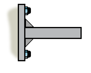
Rigid connection, welded or pin connectors that are not free to rotate but take some moment.
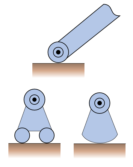
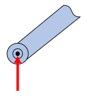
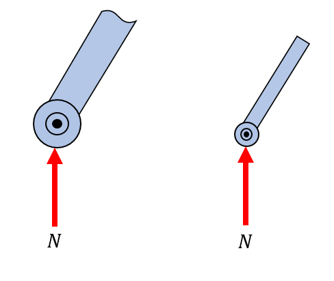
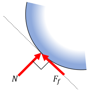
Smooth surface roller support, modelling rollers, rockers or ball supports. Can only take load in the normal direction to the supporting surface.
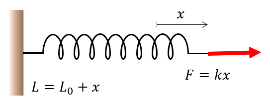
where denotes the spring stiffness in Newtons per unit length (usually .
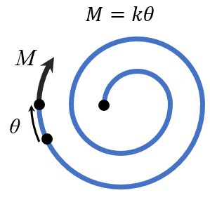
Torsional springs are loaded by an external moment, and the displacement, can be measured in radians (typically) or degrees. The relationship between the torque and angular displacement is given by the linear model
where denotes the spring stiffness in Nm/rad or Nm/deg.
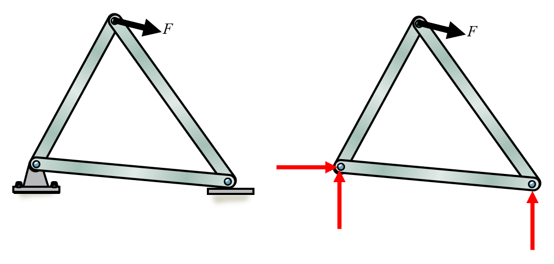
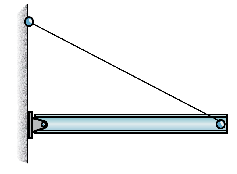
Here the supports of the structure are replaced with reaction forces. On the left we have a pin support, that can carry forces in both - and -directions, while on the right side the structure is supported in the normal direction only. The normal force is perpendicular to the ground surface. It is important to model all supports with forces, the directions do not matter. For instance the left support is modelled with a force in the positive -direction, while the external force clearly points to the right as well, meaning that once the equilibrium equations are solved, the reaction force will be negative, indicating the proper direction of this force in equilibrium.
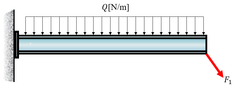
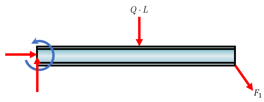
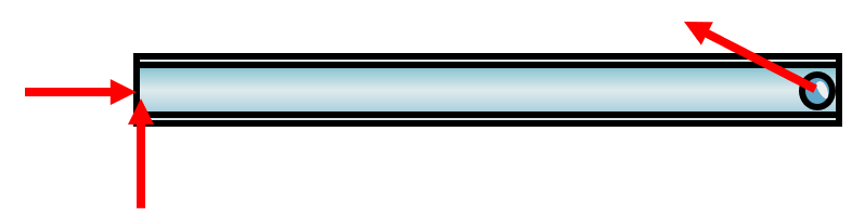
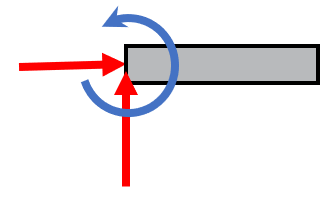
Here we have a rigid beam that is fixed to the wall, a so called cantilever beam. The supports of such beams carry both translational loads and rotation, i.e., moment.
There is a uniform load applied on the top. All distributed loads can be transformed into point loads acting on certain locations. The locations are calculated by finding the center of area and the loads are integrated. Our case is the simplest case of a distributed load, it can be transformed into a point load acting in the middle of the beam and the total load is .
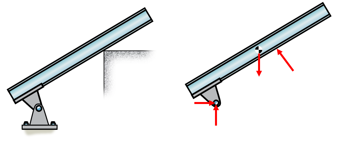
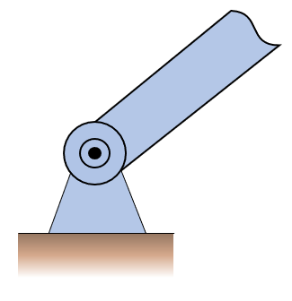
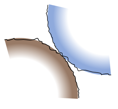
This beam is resting on an edge, which in 2D is modelled as a normal force. The support is a pin support and the beam is assumed to have a uniform mass such that its center of gravity is in the middle, denoted by the center of gravity (COG) symbol. A bodies weight vector is acting on the COG.
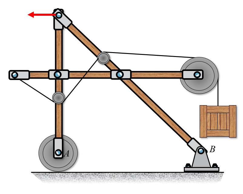
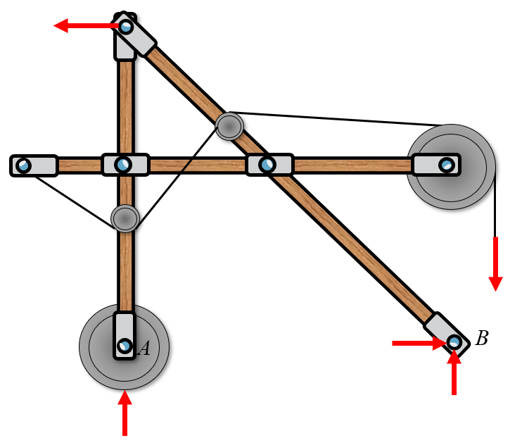
This structure may seem complicated, but the external reaction forces are modelled on the whole structure. We have a sliding support on the left side and the pin support on the right. The weight of the box is modelled by a force vector.
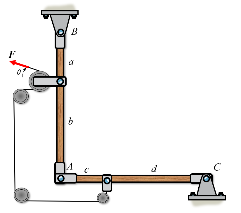
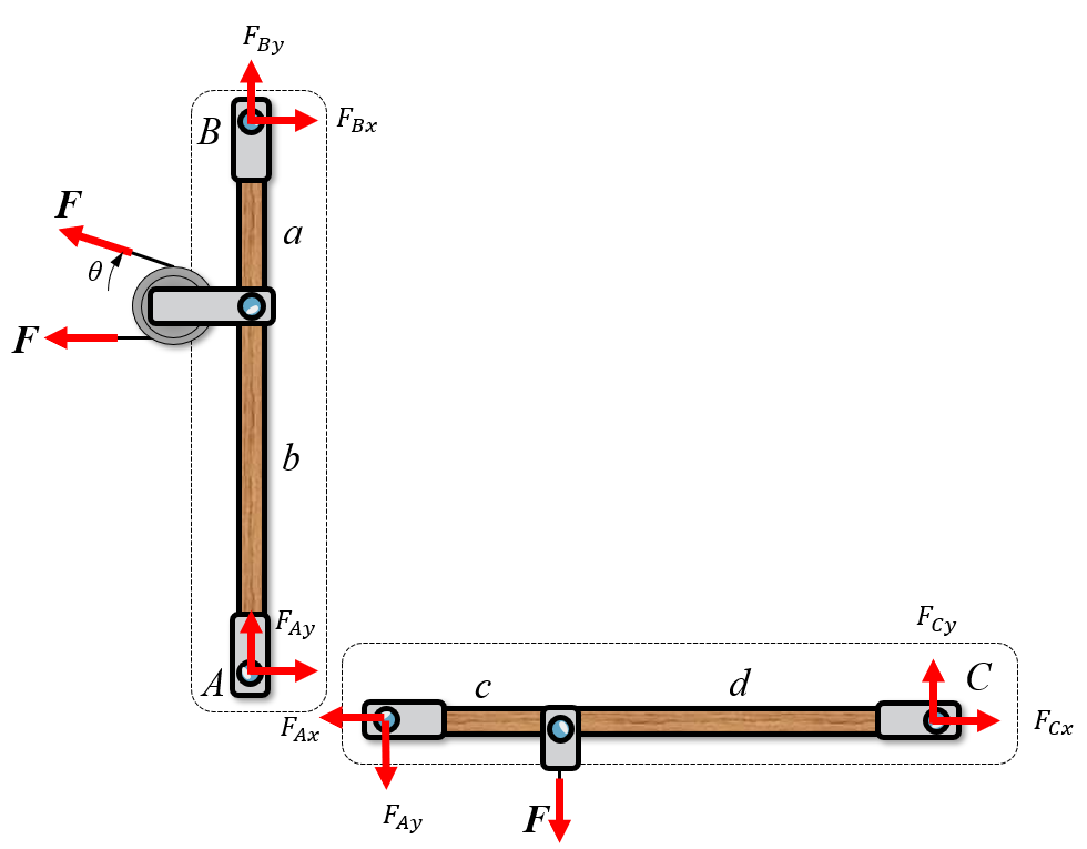
If we want to find all reaction forces, including the "internal" connector forces in point we need to split this multi-body into its separate components.
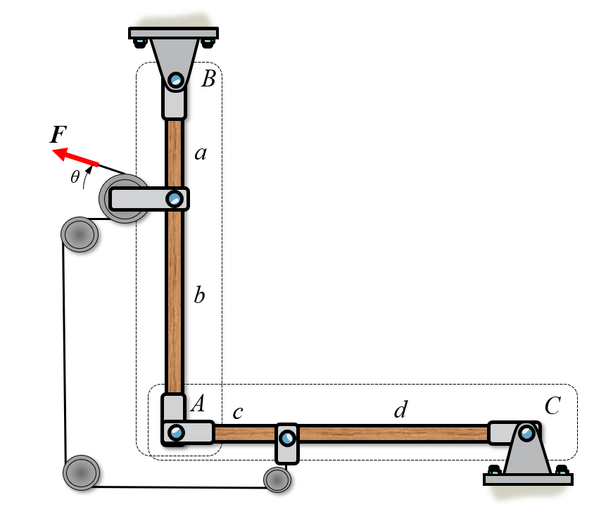
Here we have two systems, and . Now we can create a free body diagram on each system separately. We assume that the rollers are frictionless such that the force is translated without loss to body .
We can insert reaction forces according to the image below in the direction of our normal coordinate system. Special care must be taken at point for the body .