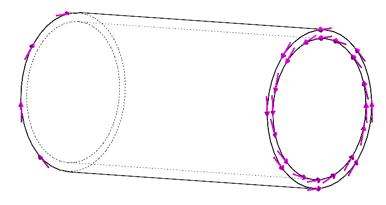
1: Consider a thin walled circular shaft under torsion. We want to find the relation between the applied Moment M and the shear stress τ.
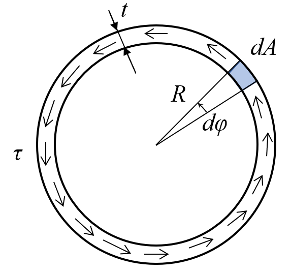
The definition of thin wall is formally that t<<R. Also, it is assumed that τ is constant in the radial direction. Taking a look at a small section of the cross-section we have
dM=TR
where dM is a infinitesimal moment and T denotes the radial force, which is given by the shear stress and area
T=τdA
If we take a closer look at the area, we can realize that it can be defined by the infinitesimal ange dφ as we "roll out" the small strip (valid if t << R)
dA=Rdφt
Then we have
dM=TR=dAτR=τtR2dφ
the total moment is the sum of all infinitesimal moments
M=∫dM=∫02πτR2dφM=2πR2tτ⇒τ=2πR2tM[m2N]
The denominator is known as the torsional resistance, W.
τmax=WM
For a solid section we have
W=2πR3=16πd3
For a thick tube we have
W=32Rπ(R4−r4)=16Dπ(D4−d4)
and since earlier, for a thin tube with a thickness of t we have
W=2πR2t
The shear stress τ will vary linearly from zero at the center of the shaft to τmax at its outer surface, this can be expressed as
τ=Rρτmax
The infinitesimal moment can also be given as the product of the moment-arm ρ and the force
dM=ρτdA
Thus the total moment is
M=∫ρτdA=∫ρRρτmaxdA
Note that Rτmax is constant, so we can pull it out of the integral, and we get
M=Rτmax∫ρ2dA
This integral is known as the polar moment of inertia.
J=∫ρ2dA
Which we can also use to compute the maximum torsional shear stress
τ=JMρ⇒τmax=JMR
So we see the relation between the polar moment of inertia J and the torsional resistance W is given by
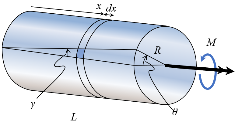
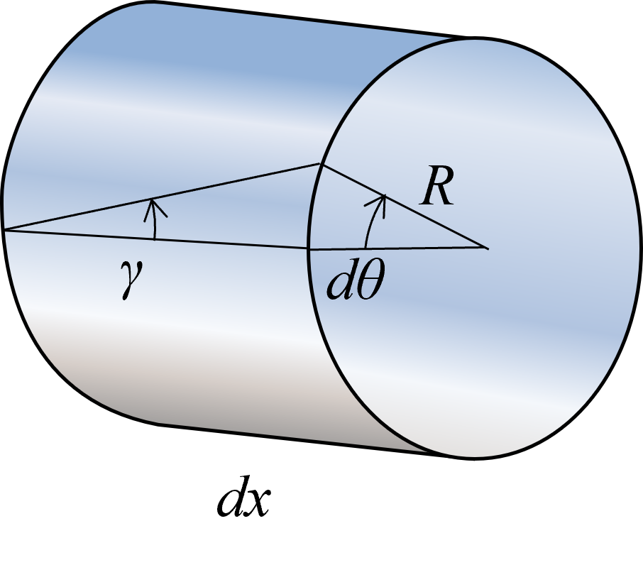
2: Consider a circular shaft under torsion. We want to find the relation between the applied Moment M and the angle of twist θ.
For small angles we have the geometric relation
γdx=Rdθ
If we assume that the material is linear elastic, Hooke's law holds and
τ=Gγ
where G is the shear modulus, and is either determined experimentally, or computed from the Young's modulus and Poisson's ratio. It can be shown that
G=2(1+ν)E
Thus we can get the relation between the twist angle and applied moment by adding up all small contributions
dθ=Rγdx=GRτdx
we know that for a solid rod τ=πR32M, so
dθ=πR42MG1dx⇒∫0θdθ=∫0LπR42MG1dx=θ=GJLM
GJ is known as the torsional rigidity. This assumes that everything is constant along the length of the rod. If something varies, then we need to integrate.
θ=∫0LG(x)J(x)M(x)dx
⚠ Note
Note that this relation is valid under small deformations and for circular cross sections. There are approximate formulas for torsional resistance (W) in various sources (check the formulary for some examples). A far more accurate method is to utilize Finite Element Analysis for more complex cross sections to determine stresses and displacements.