Download this page as a Matlab LiveScript
Table of contents
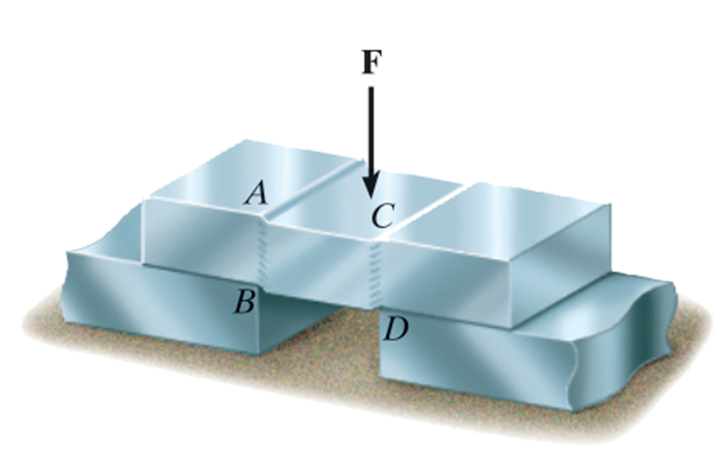
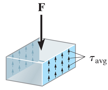
The average shear stress is given by
τ = T A \tau =\dfrac{T}{A} τ = A T where T T T A A A
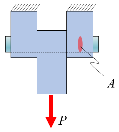
Determine the shear stress in the cylindrical pin with a cross sectional area of A A A P P P
Solution
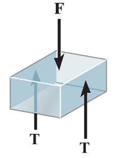
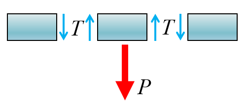
FBD of the pin
{ P − 2 T = 0 τ = T A \left\lbrace \begin{array}{ll}
P-2T=0 & \\
\tau =\dfrac{T}{A} &
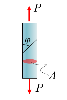
\end{array}\right. { P − 2 T = 0 τ = A T ⇒ T = P 2 , τ = P 2 A \Rightarrow T=\dfrac{P}{2},\tau =\dfrac{P}{2A} ⇒ T = 2 P , τ = 2 A P Determine the stresses in the cut at an angle φ \varphi φ
Solution
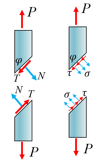
Cut and FBD
N x = N cos φ , N y = N sin φ T x = T sin φ , T y = T cos φ σ φ = N A / sin φ , τ φ = T A / sin φ
\def\arraystretch{2.5}
\begin{array}{cc}
N_x = N \cos\varphi,\; N_y=N\sin\varphi \\
T_x = T \sin\varphi,\; T_y=T\cos\varphi \\
\sigma_\varphi = \dfrac{N}{A/\sin\varphi},\quad
\tau_\varphi = \dfrac{T}{A/\sin\varphi} \\
\end{array}
N x = N cos φ , N y = N sin φ T x = T sin φ , T y = T cos φ σ φ = A / sin φ N , τ φ = A / sin φ T { N sin φ + T cos φ − P = 0 − N cos φ + T sin φ = 0 σ φ = N A / sin φ τ φ = T A / sin φ
\def\arraystretch{1.5}
\left\lbrace \begin{array}{ll}
N\;\sin \varphi +T\;\cos \varphi -P=0 & \\
-N\;\cos \varphi +T\;\sin \varphi =0 & \\
\sigma_{\varphi } =\dfrac{N}{A/\sin \varphi } & \\
\tau_{\varphi } =\dfrac{T}{A/\sin \varphi } &
\end{array}\right.
⎩ ⎨ ⎧ N sin φ + T cos φ − P = 0 − N cos φ + T sin φ = 0 σ φ = A / sin φ N τ φ = A / sin φ T ⇒ N = P sin φ , T = P sin φ , σ φ = P sin 2 φ A , τ φ = P sin φ cos φ A \Rightarrow N=P\;\sin \varphi ,\quad T=P\;\sin \varphi ,\quad \sigma_{\varphi } =\dfrac{P\;\sin^2 \varphi }{A} ,\quad \tau_{\varphi } =\dfrac{P\;\sin \varphi \;\cos \varphi }{A} ⇒ N = P sin φ , T = P sin φ , σ φ = A P sin 2 φ , τ φ = A P sin φ cos φ clear
syms N T varphi P A sigma_varphi tau_varphi
eq = [N*sin (varphi) + T*cos (varphi) - P == 0
-N*cos (varphi) + T*sin (varphi) == 0
sigma_varphi == N/(A/sin (varphi))
tau_varphi == T/(A/sin (varphi))]( T cos ( φ ) − P + N sin ( φ ) = 0 T sin ( φ ) − N cos ( φ ) = 0 σ φ = N sin ( φ ) A τ φ = T sin ( φ ) A )
\left(\begin{array}{c}
T\,\cos \left(\varphi \right)-P+N\,\sin \left(\varphi \right)=0\\
T\,\sin \left(\varphi \right)-N\,\cos \left(\varphi \right)=0\\
\sigma_{\varphi } =\frac{N\,\sin \left(\varphi \right)}{A}\\
\tau_{\varphi } =\frac{T\,\sin \left(\varphi \right)}{A}
\end{array}\right)
⎝ ⎛ T cos ( φ ) − P + N sin ( φ ) = 0 T sin ( φ ) − N cos ( φ ) = 0 σ φ = A N s i n ( φ ) τ φ = A T s i n ( φ ) ⎠ ⎞ [N,T,sigma_varphi,tau_varphi] = solve(eq, [N,T,sigma_varphi,tau_varphi]);
simplify([N,T,sigma_varphi,tau_varphi])( P sin ( φ ) P cos ( φ ) P sin ( φ ) 2 A P sin ( 2 φ ) 2 A )
\left(\begin{array}{cccc}
P\,\sin \left(\varphi \right) & P\,\cos \left(\varphi \right) & \frac{P\,{\sin \left(\varphi \right)}^2 }{A} & \frac{P\,\sin \left(2\,\varphi \right)}{2\,A}
\end{array}\right)
( P sin ( φ ) P cos ( φ ) A P s i n ( φ ) 2 2 A P s i n ( 2 φ ) ) P = 1 ; A = 1 ;
figure ; hold on
fplot(subs(N), [0 ,pi /2 ], 'linewidth' , 2 , 'DisplayName' , '$N/P$' )
fplot(subs(T), [0 ,pi /2 ], 'linewidth' , 2 , 'DisplayName' , '$T/P$' )
fplot(subs(sigma_varphi), [0 ,pi /2 ], 'linewidth' , 2 , 'DisplayName' , '$\sigma_\varphi A / P$' )
fplot(subs(tau_varphi), [0 ,pi /2 ], 'linewidth' , 2 , 'DisplayName' , '$\tau_\varphi A / P$' )
legend ('Interpreter' ,'latex' )
xlabel('$\varphi$' , 'Interpreter' ,'latex' )As we can see, the maximum shear stress is at π 4 = 45 ∘ \frac{\pi }{4}={45}^{\circ } 4 π = 45 ∘
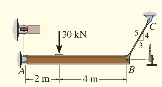
Dimension the pin in A and in B is the maximum allowable shear stress is 180MPa, use a safety factor of 1.5.
Solution
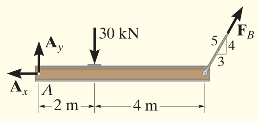
FBD of the rigid beam.
Equilibrium equations give:
{ ∑ M A = 0 : F By r AB − F G r AG = 0 ⇒ F B 4 5 ⋅ 6 − 30000 ⋅ 2 = 0 → : F Bx − A x = 0 ⇒ F B 3 5 = A x ↑ : A y − F G + F By ⇒ A y = 30000 − F B 4 5 \left\lbrace \begin{array}{ll}
\sum M_A =0:F_{\textrm{By} } r_{\textrm{AB} } -F_G r_{\textrm{AG} } =0 & \Rightarrow F_B \dfrac{4}{5}\cdot 6-30000\cdot 2=0\\
\to :F_{\textrm{Bx} } -A_x =0 & \Rightarrow F_B \dfrac{3}{5}=A_x \\
\uparrow :A_y -F_G +F_{\textrm{By} } & \Rightarrow A_y =30000-F_B \dfrac{4}{5}
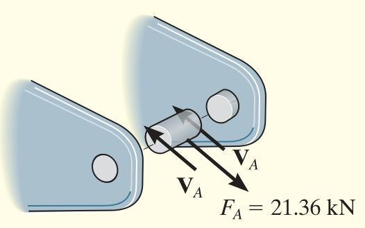
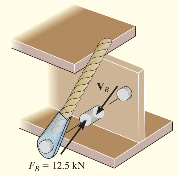
\end{array}\right. ⎩ ⎨ ⎧ ∑ M A = 0 : F By r AB − F G r AG = 0 →: F Bx − A x = 0 ↑: A y − F G + F By ⇒ F B 5 4 ⋅ 6 − 30000 ⋅ 2 = 0 ⇒ F B 5 3 = A x ⇒ A y = 30000 − F B 5 4 F A = ∣ [ A x , A y ] ∣ = A x 2 + A y 2 F_A =|\left\lbrack A_x ,A_y \right\rbrack |=\sqrt{A_x^2 +A_y^2 } F A = ∣ [ A x , A y ] ∣ = A x 2 + A y 2 V A = 1 2 F A V_A =\dfrac{1}{2}F_A V A = 2 1 F A τ A = V A A A ⇒ A A = τ A V A = ( d A 2 ) 2 π \tau_A =\dfrac{V_A }{A_A }\Rightarrow A_A =\dfrac{\tau_A }{V_A }={\left(\dfrac{d_A }{2}\right)}^2 \pi τ A = A A V A ⇒ A A = V A τ A = ( 2 d A ) 2 π V B = F B V_B =F_B V B = F B τ B = V B A B = V B ( d B 2 ) 2 π \tau_B =\dfrac{V_B }{A_B }=\dfrac{V_B }{ {\left(\dfrac{d_B }{2}\right)}^2 \pi } τ B = A B V B = ( 2 d B ) 2 π V B clear
syms d_A positive
F_A = 21360 tau = 180e6 /1.5 V_A = 1 /2 *F_A;
d_A = solve(tau == V_A / ( (d_A/2 )^2 *pi ) , d_A)d_A =
89 500 π
\frac{\sqrt{89} }{500\,\sqrt{\pi } }
500 π 89 d_A = vpa(d_A) d_A =
0.010645107772184811425477557121826
0.010645107772184811425477557121826
0.010645107772184811425477557121826 d_A = d_A*1000 d_A =
10.645107772184811425477557121826
10.645107772184811425477557121826
10.645107772184811425477557121826 syms d_B positive
V_B = 12500 ;
d_B = solve(tau == V_B/( (d_B/2 )^2 *pi ), d_B)d_B =
600 1200 π
\frac{\sqrt{600} }{1200\,\sqrt{\pi } }
1200 π 600 d_B = vpa(d_B) d_B =
0.01151647164904451597550815486773
0.01151647164904451597550815486773
0.01151647164904451597550815486773 d_B = d_B*1000 d_B =
11.51647164904451597550815486773
11.51647164904451597550815486773
11.51647164904451597550815486773 Conclusion: The pin in A needs to be at least 11mm and the pin in B needs to be at least 12mm. For easier manufacturing, just use 12mm pins in both connections.